Magnetic Effects of Electric Current for Class 10

Table of Content

  • Magnetic Effects of Electric Current
  • Introduction to Magnetism
  • Magnetic Field of Earth
  • Magnetic Effect of Current
  • Magnetic Field due to a Current-Carrying Conductor
  • Electromagnet
  • Force on a Current-Carrying Conductor in a Magnetic Field
  • Electric Motor
  • Electromagnetic Induction
  • Direct and Alternating Current
  • Electric Generator
  • Domestic Electric Circuits
  • FAQs
  • Magnetic Effects of Electric Current

    The magnetic effect of electric current is a fundamental phenomenon in physics that describes the ability of an electric current to generate a magnetic field in its surrounding space. This phenomenon was first discovered by Hans Christian Oersted in 1820 and laid the foundation for our understanding of electromagnetism. The magnetic effect of electric current is essential for various practical applications, including the operation of electric motors, generators, transformers, and many electronic devices.

    Introduction to Magnetism

    1. Magnets: Magnets are objects that have the remarkable ability to attract materials like iron, steel, nickel, and cobalt. They come in various shapes and sizes, with one of the most common types being the bar magnet. A bar magnet is a long, rectangular bar with a consistent cross-section that can attract iron, steel, nickel, and cobalt.
    2. Magnetic Poles: Every magnet possesses two distinct poles near its ends—the north pole and the south pole. The end of a freely suspended or pivoted magnet pointing towards the Earth's north direction is called the north pole, while the end pointing south is called the south pole. An essential principle of magnetism is that like magnetic poles repel each other, whereas unlike magnetic poles attract each other. In simpler terms, north repels north, south repels south, but north attracts south.
    3. Applications of Magnets: Magnets find a multitude of applications in our daily lives. They are used in radios, televisions, stereo speakers, refrigerator doors, audio and video cassette tapes, computer hard drives, toys, electric generators, electric motors, and even in medical devices like Magnetic Resonance Imaging (MRI) machines used for scanning the human body.

    Magnetic Field

    A magnetic field is a fundamental concept in physics that describes the region of influence surrounding a magnet or a current-carrying conductor. Similar to how an electric charge generates an electric field, a magnet creates a magnetic field around it. A magnetic field is the region in space where the force of attraction or repulsion due to a magnet or moving charged particles can be detected. It is a fundamental property of magnets and electric currents.

    1. Origin of Magnetic Fields: Magnetic fields can originate from two primary sources:
    2. Permanent Magnets: Certain materials, such as iron, nickel, and cobalt, possess natural magnetic properties. When these materials are magnetised, they create a magnetic field around them. These materials are often used to make permanent magnets like bar magnets.
    3. Electric Currents: Moving electric charges, such as electrons flowing through a wire, create a magnetic field. This is the basis for electromagnets.

    Effects of Magnetic Fields

    1. Compass Needle Deflection: When a compass needle is placed within a magnetic field, it aligns itself with the field lines. The north end of the compass needle points toward the magnetic north pole.
    2. Attraction and Repulsion: Magnets experience either attraction or repulsion based on the orientation of their poles. Like poles (north-north or south-south) repel each other, while opposite poles (north-south) attract.

    Magnetic Field Lines

    Magnetic field lines are imaginary lines or curves that are drawn to depict the structure and direction of a magnetic field in space.
    They represent the path and direction along which a small north magnetic pole would move if placed within the magnetic field.

    Characteristics

    1. Origin and Termination: Magnetic field lines always originate from the North pole (N-pole) of a magnet or the region where the current enters a current-carrying conductor. They terminate at the South pole (S-pole) of the magnet or the region where the current exits the conductor.
      This convention ensures that magnetic field lines create closed loops or curves, providing a continuous representation of the magnetic field.
    2. Closed and Continuous Curves: Magnetic field lines are continuous, meaning there are no gaps or interruptions in their path.
      They form closed loops, indicating that the magnetic field is continuous and flows continuously from the north pole to the south pole of a magnet or through the conductor.
    3. Non-Intersecting Lines: Magnetic field lines do not intersect or cross each other. If they were to cross, it would imply that a single point in space experiences multiple directions of magnetic force, which is not possible. The non-intersecting property ensures that the direction of the magnetic field is unique at every point.
    4. Density Near Poles: Magnetic field lines are more densely packed near the poles of a magnet or the current-carrying conductor.
      The closer spacing of field lines near the poles indicates a stronger magnetic field in those regions. As you move away from the poles, the field lines become less crowded, representing weaker magnetic fields.
    5. Tangent Indicates Direction: At any point along a magnetic field line, the direction of the magnetic field is indicated by a tangent line drawn to the field line at that specific point. The tangent line points in the direction a small north magnetic pole would move if placed at that location.
    6. Magnetic Field Lines: Tangent Indicates Direction - CREST Olympiads

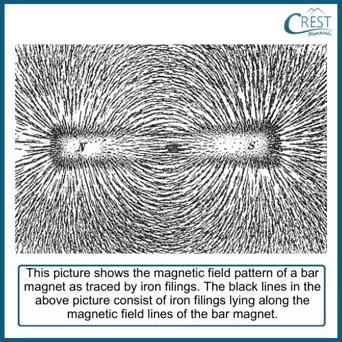
    7. Visualisation: To visualise magnetic field lines around a bar magnet, iron filings are often used. Sprinkling iron filings around a bar magnet reveals the pattern of magnetic field lines as the filings align themselves along the lines of force. This makes the otherwise invisible magnetic field visible.
    8. Magnetic Field Lines: Visualisation - CREST Olympiads

    Magnetic Field of Earth

    Earth's magnetic field is a complex phenomenon that influences the behaviour of magnetic materials on our planet. It plays a crucial role in navigation and compass use and even protects the Earth from harmful solar radiation by deflecting charged particles from the Sun, creating auroras in the polar regions.

    1. Origin of Earth's Magnetic Field: The Earth's magnetic field is generated deep within the planet, primarily in its outer core. This magnetic field is a result of complex processes involving the movement of molten iron and nickel in the Earth's liquid outer core. These materials are electrically conductive, and their motion generates electric currents. According to the geodynamo theory, these electric currents create the Earth's magnetic field through a process known as the geodynamo effect.
    2. Shape of Earth's Magnetic Field: The Earth's magnetic field is often visualised as if it were produced by an imaginary bar magnet placed at the centre of the Earth. This hypothetical bar magnet has a magnetic south pole located near the geographical north pole and a magnetic north pole near the geographical south pole. The magnetic field lines extend outward from the magnetic south pole, loop around the Earth, and re-enter at the magnetic north pole.
    3. Magnetic North and South Poles: There is an important distinction between the geographical poles and the magnetic poles of the Earth:
      The magnetic north pole is the point on the Earth's surface where the magnetic field lines point vertically downward.
      The magnetic south pole is the point where the magnetic field lines point vertically upward.
      These magnetic poles are not fixed in place and can move over time. The magnetic north pole, for instance, migrates slowly over the years.
    4. Alignment of Compass Needles: One of the most visible effects of the Earth's magnetic field is its influence on compass needles. Compass needles are essentially small magnets that align themselves with the magnetic field lines of the Earth. This alignment allows people to use compasses for navigation, with the needle pointing toward the magnetic north pole.
    5. Protection from Solar Radiation: The Earth's magnetic field serves as a protective shield against harmful solar radiation and charged particles from the Sun. This shield, known as the magnetosphere, deflects and redirects solar wind and cosmic radiation away from the Earth. This protective effect is essential for maintaining a stable and habitable environment on our planet.
    6. Variations and Reversals: The Earth's magnetic field is not constant and can undergo variations and even reversals over geological time scales. These variations are recorded in ancient rocks, where the alignment of magnetic minerals reflects the magnetic field's state at the time the rocks formed. Periodically, the magnetic field may weaken and reverse, with the magnetic north and south poles switching places.
    7. Spread of Magnetic Poles: Unlike the well-defined geographical poles, the positions of Earth's magnetic poles are not fixed points; they are spread over an area. This means that the magnetic north and south poles vary slightly in position.
    8. Inclination of Magnetic Field: The axis of Earth's magnetic field does not perfectly align with the geographical axis. It is inclined at an angle of about 15o with respect to the geographical axis. As a result, when a freely suspended magnet is influenced by the Earth's magnetic field, it doesn't align exactly with the geographical north-south axis. Instead, it makes an angle of about 15o.
    9. Earth as an Electromagnet: The current scientific understanding is that the Earth's magnetism is primarily generated by the movement of molten iron and nickel in the Earth's liquid outer core. The circulation of these conducting materials generates electric currents, which, in turn, create the Earth's magnetic field. Essentially, the Earth can be viewed as a massive electromagnet, producing the magnetic effect we observe.

    Magnetic Effect of Current

    The magnetic effect of current, also known as electromagnetism, is a fundamental phenomenon in physics that describes the relationship between electric currents and magnetic fields. The magnetic effect of current is the phenomenon where an electric current flowing through a conductor (such as a wire) creates a magnetic field in the surrounding space. This magnetic field is similar to the magnetic field produced by a permanent magnet and exhibits properties such as attraction and repulsion.

    1. Oersted's Experiment: Hans Christian Oersted's groundbreaking experiment involved demonstrating that an electric current in a wire could deflect a nearby compass needle. This experiment provided experimental evidence of the relationship between electricity and magnetism and led to the discovery of electromagnetism.
    2. Setup: Oersted arranged a simple setup with a conducting wire and a magnetic compass.
      Before turning on the electric current, the compass needle pointed north due to Earth's magnetic field.
      When he allowed the electric current to flow through the wire, the compass needle deflected from its northward orientation.
      Reversing the direction of the electric current caused the compass needle to deflect in the opposite direction.
    3. Key Observations: Oersted's crucial observations were as follows:
      When an electric current flows through a wire, it produces a magnetic field around the wire.
      The magnetic field produced by the current-carrying wire can exert a force on a nearby magnetic compass needle.
      The direction of the compass needle's deflection depended on the direction of the electric current in the wire.
    4. Significance: Oersted's Experiment demonstrated that electric currents and magnetic fields are interconnected. It provided experimental evidence for the existence of a magnetic effect produced by electric currents, laying the foundation for the field of electromagnetism.

    Magnetic Field due to a Current-Carrying Conductor

    When an electric current flows through a conductor, it generates a magnetic field around it. The magnetic field's strength and direction depend on the characteristics of the conductor such as the shape of the conductor and the magnitude and direction of the current.

    1. Magnetic Field due to Straight Current-Carrying Conductor

    The magnetic field pattern produced by a straight current-carrying conductor, often referred to as a straight wire, is characterised by concentric circles of magnetic field lines that are centred around the wire.

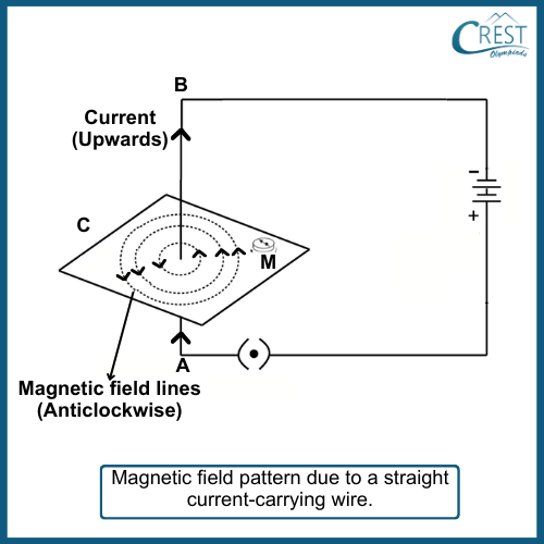
    1. Experimental Setup: Consider a straight vertical wire labelled AB, that passes through a horizontal surface (as shown in the figure below). The wire is connected to a power source, such as a battery, through a switch to allow an electric current to flow through it. This setup is used to demonstrate the magnetic field pattern.
    2. Experiment of Magnetic Field due to Current Carrying Conductor - CREST Olympiads

    3. Magnetic Field Lines: When an electric current flows through the wire AB, it generates a magnetic field in the space surrounding the wire. This magnetic field has a specific pattern that can be visualised using iron filings. When iron filings are sprinkled on the horizontal surface around the wire, they become magnetised and align themselves along the magnetic field lines.
    4. Concentric Circles: The iron filings arrange themselves in concentric circles around the wire. These circles represent the path followed by the magnetic field lines as they emanate from the wire and return to it. The circles are centred on the wire and are equidistant from each other.
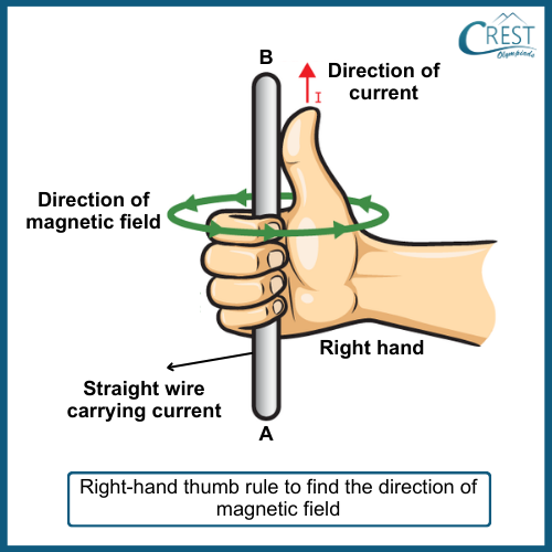
    5. Maxwell's Right-Hand Thumb Rule: The direction of the magnetic field lines around a straight current-carrying wire can be determined using Maxwell's right-hand thumb rule:
      If you imagine grasping the wire with your right hand, such that your thumb points in the direction of the current (from A to B in the case of upward current flow), the direction in which your fingers curl around the wire represents the direction of the magnetic field lines.
      In this example, the fingers of your right hand would curl in the anticlockwise direction, indicating that the magnetic field lines circulate counterclockwise around the wire.
    6. Maxwell's Right-Hand Thumb Rule - CREST Olympiads

    7. Effect of Current Strength and Distance: The strength of the magnetic field produced by a straight current-carrying wire is directly proportional to the magnitude of the current passing through the wire. Increasing the current results in a stronger magnetic field.
      Conversely, the strength of the magnetic field decreases as you move farther away from the wire. The concentric circles representing the magnetic field lines become larger as you move away, indicating a decrease in magnetic field strength.
    8. Changing Current Direction: If the direction of the electric current in the wire is reversed (i.e., flowing from B to A), the direction of the magnetic field lines also reverses. The magnetic field lines will now form concentric circles in the opposite direction, clockwise, around the wire.

    2. Magnetic Field Pattern due to a Circular Loop (or Circular Wire) Carrying Current

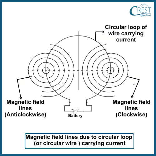
    When an electric current flows through a circular loop of wire, it generates a magnetic field around the loop. This magnetic field consists of concentric circles centred on the wire loop. Each concentric circle represents the path taken by a magnetic field line as it encircles the wire loop.

    1. Straight Magnetic Field at the Center: At the exact centre of the circular loop, the magnetic field lines are straight and perpendicular to the plane of the loop. This is a unique point, often called the "centre of the magnetic field," and it experiences the strongest magnetic field. All the magnetic field lines pass through this point in the same direction, resulting in a strong magnetic field.
    2. Factors Affecting Magnetic Field Strength:
      Directly Proportional to Current (I):
      The strength of the magnetic field produced by the circular loop is directly proportional to the amount of electric current flowing through the loop. This means that increasing the current will result in a stronger magnetic field.
      Directly Proportional to the Number of Turns (N): If the circular loop consists of multiple turns of wire (a coil), the magnetic field strength is directly proportional to the number of turns. More turns lead to a stronger magnetic field.
      Inversely Proportional to Distance (r): The strength of the magnetic field decreases as you move farther away from the circular loop. It's inversely proportional to the distance from the conductor. In other words, increasing the distance from the loop will result in a weaker magnetic field.
    3. Concentric Circles Near the Loop: As you move away from the centre of the circular loop towards the outer edges of the loop, the magnetic field lines form concentric circles around the wire. These circles represent the path that a magnetic field line takes as it encircles the wire loop. The magnetic field is stronger near the loop and gradually decreases in strength as you move farther away from it.
    4. Magnetic Field Pattern due to a Circular Loop (or Circular Wire) Carrying Current - CREST Olympiads

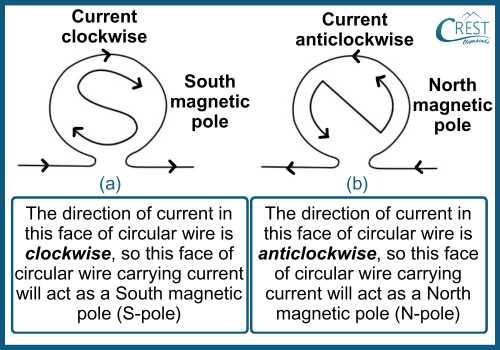
    5. Polarity and Clock Face Rule: A circular loop carrying current behaves like a magnetic dipole, which means it has two magnetic poles: a north pole (N) and a south pole (S). The polarity (whether it's N or S) depends on the direction of the current flow.
      If the electric current flows clockwise when viewed from the front of the loop, the front face of the loop behaves like a south magnetic pole (S).
      If the electric current flows counterclockwise when viewed from the front, the front face of the loop behaves like a north magnetic pole (N).
    6. Polarity and Clock Face Rule - CREST Olympiads

    3. Magnetic Field due to a Solenoid

    1. Structure of a Solenoid: A solenoid is a coil of wire wound into a tightly packed, helical (spiral) shape. It consists of many closely spaced turns or loops of wire. When an  electric current flows through this coiled wire, it creates a magnetic field around and inside the solenoid.
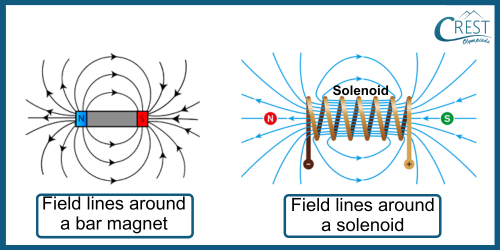
    2. Magnetic Field Lines: The magnetic field produced by a solenoid is similar in shape to that of a bar magnet. It forms closed loops of magnetic field lines that extend from one end of the solenoid to the other, creating a continuous path for the magnetic field.
    3. Uniform Magnetic Field Inside: One of the key characteristics of a solenoid is that it produces a remarkably uniform magnetic field inside its coil. This means that the strength and direction of the magnetic field remain consistent throughout the interior of the solenoid. The field lines inside the solenoid run parallel to each other, contributing to this uniformity.
    4. Field Strength Variation Along the Length: As you move towards the ends of the solenoid, the strength of the magnetic field gradually decreases. The magnetic field is strongest near the centre of the solenoid, which corresponds to the middle of its coil. This decrease in field strength as you move away from the centre is due to the magnetic field lines spreading out and looping around the ends of the solenoid.
    5. Magnetic Field Outside the Solenoid: Outside the solenoid, the magnetic field is both non-uniform and relatively weak compared to the field inside. The magnetic field lines emerge from one end of the solenoid, often referred to as the north pole (N-pole), and loop around to the other end, often referred to as the south pole (S-pole). These field lines don't form closed loops outside the solenoid.
    6. Polarity of a Solenoid: Similar to a bar magnet, a solenoid exhibits polarity. One end of the solenoid behaves as a north pole (N-pole), while the other end acts as a south pole (S-pole). The direction of the magnetic field lines inside the solenoid runs from the south pole to the north pole. This direction is consistent with the direction of conventional current flow within the solenoid.
    7. Magnetic Field Strength Factors: The strength of the magnetic field produced by a solenoid depends on several factors:
      Number of Turns (N): Increasing the number of turns of wire in the solenoid increases the strength of the magnetic field. More turns mean more field lines and greater field strength.
      Current (I): A higher current flowing through the solenoid results in a stronger magnetic field. This relationship is linear, so doubling the current will double the field strength.
      Core Material: The choice of core material inside the solenoid can also affect the magnetic field strength. Using a ferromagnetic material like soft iron as the core enhances the magnetism produced by the solenoid. This principle is fundamental in the operation of electromagnets.
     Learn more about Electricity

    Electromagnet

    Electromagnets are temporary magnets that are created by the magnetic effect of an electric current.

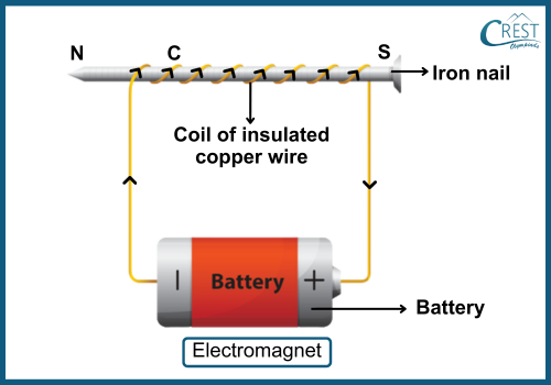
    1. Construction of an Electromagnet: An electromagnet consists of a coil of insulated copper wire wound around a soft iron core.
      The soft iron core is essential as it gets magnetised when an electric current flows through the coil, creating a magnetic field.
    2. Construction of an Electromagnet - CREST Olympiads

    3. Operation of an Electromagnet: When an electric current flows through the coil of an electromagnet, it generates a magnetic field.
      The soft iron core, being a ferromagnetic material, gets magnetised by induction due to the magnetic field created by the coil.
      This combination of the coil and the magnetised iron core creates a strong magnetic field around the electromagnet.
      Importantly, the electromagnet only exhibits magnetism when the current is flowing through the coil. As soon as the current is switched off, the magnetic properties of the iron core disappear.
    4. Core Material: The core of an electromagnet is typically made of soft iron.
      Soft iron is preferred because it loses all its magnetism when the current in the coil is interrupted.
      If a different material like steel is used for the core, it may retain some magnetism when the current is switched off, turning it into a permanent magnet. This is why steel is not used for making electromagnets.
    5. Shapes and Sizes: Electromagnets can be designed in various shapes and sizes to suit specific applications.
      Common shapes include straight bar-type electromagnets and U-shaped electromagnets.
    6. Factors Affecting Strength: Several factors influence the strength of an electromagnet:
      Number of Turns: Increasing the number of turns of wire in the coil enhances the strength of the electromagnet. More turns result in more magnetic field lines.
      Current Flow: Increasing the current flowing through the coil also boosts the strength of the electromagnet. A higher current produces a stronger magnetic field.
      Length of Air Gap: Reducing the length of the air gap between the poles of the electromagnet increases its strength. Electromagnets with smaller air gaps between the poles tend to be stronger.
    7. Polarity of Electromagnet: Like permanent magnets, electromagnets also exhibit polarity.
      The polarity of an electromagnet can be determined using the clock face rule:
      Viewing the electromagnet from one end, you can identify the direction of the current flow in the coil. If it's clockwise, that end becomes the South pole (S-pole); if it's anticlockwise, it becomes the North pole (N-pole).
      For example, if you view the electromagnet from the left end and observe that the current flows counterclockwise, then the left end is the N-pole. If you view it from the right end and see clockwise current flow, the right end is the S-pole.
    8. Controllability: One significant advantage of electromagnets is their controllability. Their strength can be easily adjusted by changing the number of turns in the coil or altering the current flowing through it. This feature makes electromagnets suitable for various applications where precise control of the magnetic field strength is required.

    Force on a Current-Carrying Conductor in a Magnetic Field

    The force experienced by a current-carrying conductor when placed in a magnetic field is a fundamental principle in electromagnetism. This phenomenon is described by the interaction between the magnetic field and the electric current flowing through the conductor.

    When a current-carrying conductor is placed in a magnetic field, it experiences a force. The force on the conductor is governed by the interaction between the magnetic field and the electric current flowing through the conductor.

    1. Force Direction: The force on the conductor is always perpendicular to both the direction of the electric current in the conductor and the direction of the magnetic field.
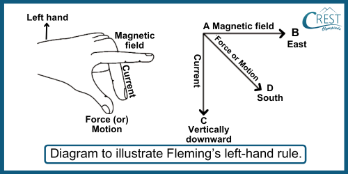
      This force follows a specific rule known as Fleming's Left-Hand Rule, which allows you to determine the relationship between the magnetic field, current, and force direction. The rule is named after the scientist John Ambrose Fleming.
    2. Fleming's Left-Hand Rule: To use Fleming's Left-Hand Rule, imagine your left hand with your thumb, forefinger, and middle finger at right angles to each other.
      Point your forefinger in the direction of the magnetic field (from north to south).
      Point your middle finger in the direction of the electric current (the direction in which positive charges move, conventionally from the positive terminal to the negative terminal of a battery or power source).
      Your thumb will then point in the direction of the force acting on the conductor.
    3. Fleming's Left-Hand Rule - CREST Olympiads

    4. Maximum Force: The force on the conductor is at its maximum when the direction of the current is perpendicular to the direction of the magnetic field.
      In this case, the force is strong enough to cause noticeable motion or deflection of the conductor.
    5. Zero Force: When the direction of the current and the direction of the magnetic field are parallel or aligned (in the same direction), the force on the conductor is zero.
      This means that there is no force acting on the conductor, and it remains stationary.
    6. Reversing Force Direction: You can reverse the direction of the force on the conductor by either reversing the direction of the current (changing the direction of electron flow) or reversing the direction of the magnetic field.
    7. Applications: Understanding the force on a current-carrying conductor in a magnetic field is crucial for the operation of various electrical devices and instruments:
      Electric motors use this principle to convert electrical energy into mechanical motion.
      Generators operate on the reverse principle, where mechanical motion induces an electric current.
      Loudspeakers use this force to vibrate a diaphragm and produce sound.
      Measuring instruments like ammeters and galvanometers utilise the interaction between current and magnetic fields to indicate current strength.

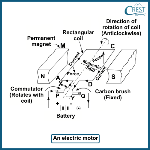
    Electric Motor

    An electric motor is a device that converts electrical energy into mechanical energy, specifically rotational motion. It operates based on the principles of electromagnetism and magnetic field interactions with electric currents. Electric motors are widely used in numerous applications, from powering household appliances like fans and washing machines to industrial machinery and electric vehicles.

    Principle of Operation: Electric motors operate on the fundamental principle that when a current-carrying conductor (usually in the form of a coil of wire) is placed within a magnetic field, it experiences a mechanical force. This force causes the conductor to move, and if this movement is constrained and controlled, it can be used to perform work.

    Key Components of an Electric Motor:

    1. Armature: The armature is the core component of the motor and consists of a coil of wire typically wound around a soft iron core. This coil is designed to carry an electric current.
    2. Stator: The stator is the stationary part of the motor that generates a magnetic field. It usually includes permanent magnets or electromagnetic coils. The stator's magnetic field interacts with the armature's current to produce the motor's motion.
    3. Commutator: In many electric motors, especially direct current (DC) motors, a commutator is used to reverse the direction of current in the armature coil as it rotates. The commutator is a split copper ring attached to the armature shaft that periodically changes contact with brushes. This reversal of current direction ensures continuous rotation of the armature.
    4. Brushes: Carbon brushes are stationary components that make electrical contact with the rotating commutator. They allow the electric current to flow into the armature coil without the need for physical wiring connections that would twist as the motor rotates.
    5. Shaft: The shaft is connected to the armature and is responsible for transmitting the mechanical motion generated by the armature to the external device or load being driven by the motor.

    Working of an Electric Motor:

    When a voltage is applied to the motor, electric current flows through the armature coil.

    The current-carrying armature coil generates a magnetic field around itself, which interacts with the magnetic field produced by the stator (permanent magnets or electromagnetic coils).

    According to Fleming's left-hand rule, these magnetic fields exert mechanical forces on the armature coil, causing it to rotate. The direction of rotation depends on the relative orientations of the armature's current and the stator's magnetic field.

    As the armature begins to rotate, the commutator periodically reverses the direction of current flow in the coil, ensuring that the armature continues to turn in the same direction. This reversal happens at specific points in the coil's rotation, often when it reaches a vertical or horizontal position.

    The mechanical motion generated by the armature's rotation can be used to perform various tasks, such as driving a fan, turning the wheels of a car, or powering industrial machinery.

    Working of an Electric Motor - CREST Olympiads

    Electromagnetic Induction

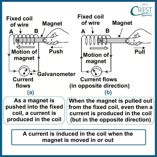
    We've previously learned that electric current can create magnetism. However, the reverse is also true: magnetism or magnets can generate electric current. This phenomenon of generating electricity from magnetism is called electromagnetic induction.
    This phenomenon was discovered by British scientist Michael Faraday and independently by American scientist Joseph Henry in the early 19th century. Electromagnetic induction plays a crucial role in various aspects of our daily lives and has numerous applications in technology and engineering.
    At its core, electromagnetic induction is based on the relationship between magnetic fields and electric currents. When there is a change in the magnetic field surrounding a conductor, it induces an electromotive force (EMF) or voltage in the conductor. If the conductor forms a closed loop (like a wire), this induced EMF causes an electric current to flow through the circuit.

    Induced Current: The electric current that's created in the conductor due to electromagnetic induction is called the induced current. It's like magic because you're making electricity without needing a battery or power outlet.

    Electromagnetic Induction: Induced Current - CREST OLympiads

    Michael Faraday and Joseph Henry’s Observations:

    Michael Faraday and Joseph Henry were pioneering scientists in the field of electromagnetism, and their observations regarding electromagnetic induction were pivotal in understanding this phenomenon.

    Key observations made by Faraday and Henry regarding electromagnetic induction:

    1. Current Induction by Relative Motion: Faraday and Henry independently observed that a current is induced in a coil of wire when there is relative motion between the coil and a magnet. This means that if you move a magnet in and out of a coil or move a coil around a stationary magnet, an electric current is produced in the wire.
    2. No Current in Stationary Conditions: They also noted that no current is induced in the coil when both the coil and the magnet remain stationary relative to each other. In other words, electromagnetic induction only occurs when there is a change in the magnetic field strength within the coil.
    3. Change in Direction with Reversal: Faraday and Henry found that the direction of the induced current depends on the direction of the relative motion between the coil and the magnet. If the magnet's motion is reversed, the induced current's direction also reverses. This demonstrated the principle of reversibility in electromagnetic induction.
    4. Increase in Magnitude: They observed that the magnitude of the induced current can be increased by several factors:
    • Number of Turns: Increasing the number of turns in the coil amplifies the induced current.
    • Strength of the Magnet: Using a stronger magnet leads to a larger induced current.
    • Speed of Relative Motion: Faster relative motion between the magnet and the coil results in a higher induced current.
    • Use of a Soft Iron Core: Winding the coil around a soft iron core enhances the induction effect. This is because iron is more easily magnetised and demagnetized.
    • Production of Alternating Current (AC): Faraday and Henry's experiments revealed that the induced current changes direction continuously when the magnet is moved back and forth. This produces an alternating current (AC) in the coil.

    These observations laid the foundation for the understanding of electromagnetic induction, which, in turn, became a fundamental principle in the development of electrical generators and transformers.

    Fleming's Right-Hand Rule

    Fleming's Right-Hand Rule is a simple method used in physics to determine the direction of induced current in a conductor when it moves in a magnetic field. It involves holding your right hand with the thumb, forefinger, and centre finger at right angles to each other.

    Thumb (T): Points in the direction of the conductor's motion.

    Forefinger (F): Points in the direction of the magnetic field lines.

    Center Finger (C): Indicates the direction of the induced current.

    To use the rule, align your thumb with the motion of the conductor and your forefinger with the magnetic field. Your centre finger will then show the direction of the induced current. It's a useful tool in understanding electromagnetic induction, especially in scenarios like electric generators.

    Direct and Alternating Current

    Direct Current (D.C.)

    Direct current is an electric current that flows consistently in one direction with a fixed polarity. Electrons move from the negative terminal to the positive terminal of a voltage source.

    Sources: D.C. is commonly produced by devices like batteries (e.g., dry cells, car batteries), solar panels, and D.C. generators.

    Characteristics:

    1. The flow of electrons is unidirectional, from negative to positive terminals.
    2. The magnitude and direction of current remain constant over time.
    3. D.C. is typically represented as a straight line on a graph of current over time.

    Alternating Current (A.C.)

    Alternating current is an electric current that reverses its direction periodically, typically at a fixed frequency. This means the flow of electrons alternates back and forth.

    Sources: A.C. is commonly generated by power stations, alternators in vehicles, and most electrical grids.

    Characteristics:

    1. The direction of current alternates in cycles, typically at 50 or 60 Hz (hertz) in many countries.
    2. The magnitude of current varies sinusoidally with time, creating a wave-like pattern on a graph.
    3. A.C. is well-suited for long-distance transmission due to lower energy losses compared to D.C.

    Electric Generator

    An electric generator is a device that converts mechanical energy into electrical energy. It plays a crucial role in generating the electricity we use in our daily lives.

    Principle of Electric Generator

    An electric generator operates based on the principle of electromagnetic induction, which was discovered by Michael Faraday. According to Faraday's law of electromagnetic induction, when a conductor (usually a coil of wire) is moved within a magnetic field, an electromotive force (EMF) or voltage is induced in the conductor. If this conductor is part of a closed electrical circuit, it causes an electric current to flow.

    Working of an Electric Generator

    1. Rotor or Armature: The core component of an electric generator is the rotor or armature, which is typically a coil of wire. This rotor is mounted on a shaft, and its purpose is to rotate within a magnetic field.
    2. Stator: The stator is a stationary part of the generator that produces a stable magnetic field. It surrounds the rotor and ensures that there is a constant magnetic field for the rotor to interact with.
    3. Mechanical Energy Source: Electric generators require an external source of mechanical energy to turn the rotor. Various sources can provide this mechanical energy, including steam turbines, water turbines, gas turbines, internal combustion engines, and wind turbines.
    4. Generation of Electric Current: As the rotor spins within the magnetic field created by the stator, it cuts across the magnetic field lines, which induces an electromotive force (EMF) or voltage across the rotor coil. If the generator produces alternating current (AC), this induced EMF results in an alternating voltage. If it's a direct current (DC) generator, the commutator and brushes convert the alternating voltage into direct current.
    5. External Load: The generated electrical energy is then made available through the generator's terminals and can be connected to an external electrical circuit or load, such as homes, industries, or devices, to provide power.

    Working of an Electric Generator

    1. A mechanical energy source, such as a steam turbine, water turbine, or internal combustion engine, is used to rotate the coil within the magnetic field.
    2. As the coil rotates, it continuously cuts the magnetic field lines.
    3. According to Faraday's law, an EMF is induced in the coil, creating an electric potential difference (voltage) between its terminals.
    4. When an external electrical circuit is connected to the generator, the induced voltage causes an electric current to flow through the circuit.
    5. If the generator produces A.C., the voltage and current continuously change direction, while in the case of a D.C. generator, the commutator ensures that the current flows in one direction.

    Types of Electric Generators

    1. Alternating Current Generator (A.C. Generator)

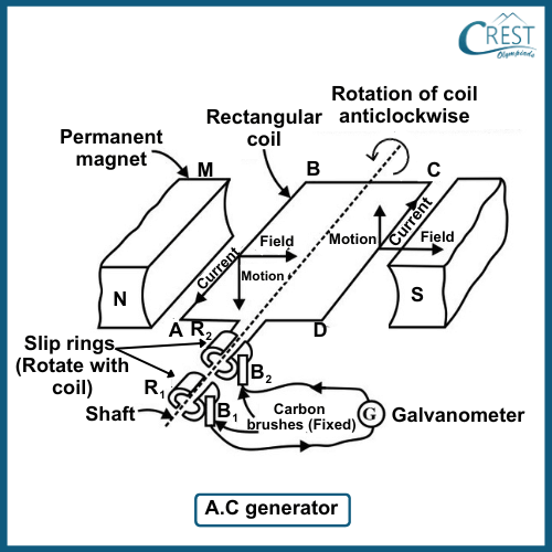
    1. An A.C. generator, also known as an alternator, produces alternating current (A.C.).
    2. In an A.C. generator, a rectangular coil of wire is rotated rapidly within a magnetic field created by a horseshoe-type magnet.
    3. As the coil rotates, it cuts across magnetic field lines, which induces an alternating current in the coil.
    4. A.C. generators are commonly used in power stations and are responsible for producing the electricity supplied to homes and industries.
    5. Electric Generators: Alternating Current Generator - CREST Olympiads

    2. Direct Current Generator (D.C. Generator)

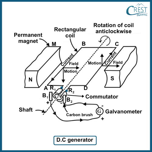
    1. A D.C. generator produces direct current (D.C.).
    2. Similar to an A.C. generator, it consists of a rotating coil within a magnetic field.
    3. However, in a D.C. generator, a commutator and brushes are used to convert the induced alternating current into direct current.
    4. D.C. generators are used in applications where a steady, unidirectional current is required, such as in batteries and some industrial processes.
    5. Electric Generators: Direct Current Generator - CREST Olympiads

    Domestic Electric Circuits

    Domestic electric circuits, often referred to as domestic wiring, are the electrical systems installed in homes to distribute electricity safely and efficiently to power various appliances and devices. These circuits are designed with several key components and safety measures to ensure the safe and reliable supply of electricity within a household.

    Key elements and concepts of domestic electric circuits:

    1. Electric Supply: Electricity is generated at power stations and then transmitted over long distances through high-voltage power lines. It is brought to our homes by two thick copper or aluminium wires, usually suspended on electric poles or routed through underground cables.
    2. Live and Neutral Wires: From the electric pole or underground cables, two primary insulated wires enter our homes: the live wire and the neutral wire. The live wire carries electricity at a high potential (usually around 220 volts in many regions), while the neutral wire is at ground potential (0 volts). The potential difference between the live and neutral wires provides the electrical voltage available for use in homes.
    3. Earth Wire: Alongside the live and neutral wires, there is a third wire called the earth wire. It is connected to a copper plate buried deep in the ground near the house or at the nearest electric substation. The earth wire is a safety measure and helps prevent electric shocks by providing a path for excess current to safely dissipate into the earth.
    4. Distribution Box: The live and neutral wires enter a distribution box or fuse box located inside the house. This box contains several crucial components:
    5. Main Fuse: A high-rated fuse (usually around 50 amperes) is placed in the live wire. It serves as the first line of defence against excessive current flow. If the current exceeds the rated value, this fuse will blow, disconnecting the power supply.
    6. Electricity Metre: This device records the amount of electrical energy consumed in kilowatt-hours (kWh) and helps determine billing.
    7. Main Switch: The main switch allows homeowners to disconnect the electricity supply when needed, such as for maintenance or in case of electrical faults.
    8. Consumer's Fuse: After the main switch, there is another fuse in the live wire known as the consumer's fuse. This fuse is specific to the power circuit (for high-power devices) and is typically rated at 15 amperes. There may also be a separate fuse for the lighting circuit (for low-power devices) rated at 5 amperes.
    9. Parallel Wiring: Inside each room, electrical appliances like bulbs, fans, sockets, and switches are connected in parallel across the live and neutral wires. Parallel wiring ensures that if one appliance fails or is switched off, it doesn't affect the operation of other appliances.
    10. Switches and Safety: All electrical appliances are equipped with switches that are placed in the live wire. Placing switches in the live wire ensures that when an appliance is switched off, it is effectively disconnected from the live wire, reducing the risk of electric shock. Safety is a paramount concern in domestic wiring.
    11. Earthing of Appliances: To prevent electric shocks, the metal cases of electrical appliances with a heavy current draw, such as electric irons, water heaters, and refrigerators, are earthed. This involves connecting the metal casing of the appliance to the earth wire via a three-pin plug, ensuring that if the live wire touches the metal case, the current flows safely into the earth wire.

    Electric Fuse

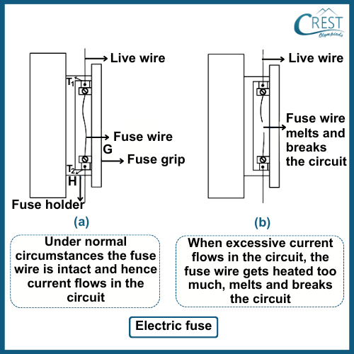
    A fuse is a safety device placed in electrical circuits to protect against excessive current flow. It consists of a short length of thin wire made of a material (e.g., tin) with a low melting point.

    1. Function: When the current in the circuit exceeds the rated value of the fuse, the fuse wire heats up due to the heating effect of the current. Once the temperature reaches the melting point, the fuse wire melts and breaks the circuit, disconnecting the power supply.
    2. Types: Fuses are available in different ratings, such as 1 A, 5 A, 10 A, 15 A, etc., to match the maximum current capacity of the circuit they protect.
    3. Placement: Fuses are typically placed at various points in domestic wiring, such as the main switchboard, individual appliances, or circuits.
    4. Advantages: Fuses provide a cost-effective and reliable means of protecting circuits and appliances from damage due to short circuits and overloads.
    5. Labelled Diagram of Electric Fuse - CREST Olympiads

    Short Circuiting and Overloading

    Short Circuiting

    A short circuit occurs when the live wire (L) and the neutral wire (N) come into direct contact with each other due to damaged or frayed insulation. This results in a low-resistance path with minimal or no resistance.

    1. Causes: Short circuits can be caused by damaged wires, frayed insulation, exposed conductors, or faulty electrical connections.
    2. Hazards: Short circuits can lead to a significant increase in current flow through the circuit, causing wires to overheat and potentially start a fire.
      The excessive current can also damage electrical appliances and pose a risk of electric shock to anyone in contact with the affected circuit.
    3. Protection: To protect against short circuits, electrical systems are equipped with fuses or circuit breakers. These devices disconnect the circuit when a short circuit occurs, preventing further damage.

    Overloading

    Overloading happens when the total electrical load on a circuit exceeds its capacity or rating. This can occur when too many high-power appliances are connected to a single circuit or when an appliance draws more current than the circuit can handle.

    1. Causes: Overloading can result from simultaneously running power-hungry appliances like electric irons, heaters, or air conditioners on the same circuit.
    2. Hazards: Overloaded circuits can overheat, leading to insulation damage and the risk of electrical fires.
      Continuous overloading can also damage appliances and reduce their lifespan.
    3. Protection: Overloading can be prevented by distributing appliances across different circuits and avoiding the simultaneous operation of high-power devices. Circuit breakers or fuses protect against overloads by disconnecting the circuit when the current exceeds the rated capacity.

     Learn more about Sources of Energy

    Frequently Asked Questions

    1. Why does reversing the direction of the current in a conductor reverse the direction of the magnetic field?

    The direction of the magnetic field is determined by the right-hand rule: if you point your thumb in the direction of the current, the curled fingers show the direction of the magnetic field. When the current reverses direction, the magnetic field also reverses, as the orientation of the charges changes.

    2. How are magnetic materials different from non-magnetic materials at the atomic level?

    In magnetic materials, the magnetic moments of atoms (caused by the movement of electrons) align in a particular direction, creating a net magnetic field. In non-magnetic materials, these magnetic moments are randomly oriented, cancelling each other out and resulting in no overall magnetic effect.

    3. What is the principle behind the magnetic effect of current?

    The magnetic effect of current is based on Oersted’s experiment, which demonstrated that a current-carrying conductor produces a magnetic field around it. This principle forms the basis for devices like electromagnets and electric motors, where electric currents are used to create controlled magnetic fields.

    4. How does an electric motor convert electrical energy into mechanical energy?

    An electric motor works on the principle of the force on a current-carrying conductor in a magnetic field. When current flows through a coil placed in a magnetic field, the coil experiences a force that causes it to rotate, converting electrical energy into rotational mechanical energy.

    5. How does the speed of motion of a conductor affect the induced current in electromagnetic induction?

    The speed at which a conductor moves through a magnetic field affects the amount of induced current. Faster motion through the magnetic field results in a greater change in magnetic flux, leading to a higher induced current.

    Quick Video Recap

    In this section, you will find interesting and well-explained topic-wise video summary of the topic, perfect for quick revision before your Olympiad exams.

    YouTube Video
    ×

    Share Your Feedback

    CREST Olympiads has launched this initiative to provide free reading and practice material. In order to make this content more useful, we solicit your feedback.

    Do share improvements at info@crestolympiads.com. Please mention the URL of the page and topic name with improvements needed. You may include screenshots, URLs of other sites, etc. which can help our Subject Experts to understand your suggestions easily.

    Other Science Related Topics for Class 10

    Other Subjects for Class 10

    70%