Light - Class 8 Notes & Olympiad Questions

Light - Class 8 Science

  • Some Key Points about Light
  • Reflection of Light
  • Plane Mirrors
  • Spherical Mirrors
  • Refraction of Light
  • Dispersion
  • Lenses
  • The Human Eye
  • Defects of Vision
  • Solved Questions on Light
  • Some Key Points about Light

    Nature of Light: Light is a form of energy that allows us to see the world around us. It travels in waves, like ripples in water, but it doesn't need a material medium to move through – it can travel through empty space.

    Speed of Light: Light is incredibly fast and travels at a speed of about 186,282 miles per second (or 299,792,458 meters per second), which is why we often say "lightning-fast."

    Luminous and Non-Luminous Objects: Some things, like the Sun, light bulbs, and stars, emit their own light and are called luminous objects. Others, like your toys or furniture, don't emit light and are called non-luminous objects.

    Reflection: When light hits a surface and bounces back, we call it reflection. Mirrors work by reflecting light, allowing us to see our reflections.

    Refraction: Light can change direction when it passes from one material to another. This bending of light is called refraction. It's what makes objects look like they're in a different place when you put a straw in a glass of water.

    Rectilinear Propagation: Light travels in straight lines. This property is called rectilinear propagation, and it's why we can see shadows behind objects.

    Colours and Spectrum: White light, like sunlight, is actually made up of many different colours. When light passes through a prism, it splits into a rainbow-like spectrum of colours. This is called dispersion.

    Optics and Lenses: Lenses, like those in glasses or cameras, use the properties of light to help us see better. Convex lenses bend light to bring things closer, while concave lenses spread light out.

    Human Eye: Our eyes are amazing organs that receive light, focus it using a lens, and create images on the retina. Special cells called rods and cones help us see in different lighting conditions and colours.

    Applications: Light has countless applications in our daily lives, from lighting up our homes to transmitting information through optical fibres and even allowing us to communicate using lasers.

    Reflection of Light

    When light strikes a smooth and polished surface, such as a mirror, it bounces back. This phenomenon is known as reflection, and it's the reason we can see our own reflection in a mirror.

    Types of Reflection

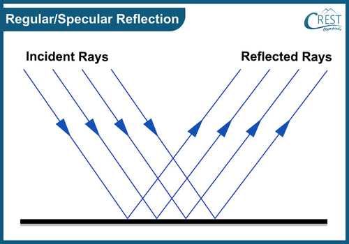
    1. Regular/Specular Reflection

    a) This type of reflection takes place on smooth and polished surfaces, such as mirrors or calm water.
    b) It results in a well-defined and clear reflection, where the angle at which light hits the surface (angle of incidence) is equal to the angle at which it bounces off (angle of reflection).
    c) Regular reflection provides us with sharp and distinct images of objects, like seeing yourself in a mirror.

    Diagram of Regular or Specular Reflection - Science Grade 8

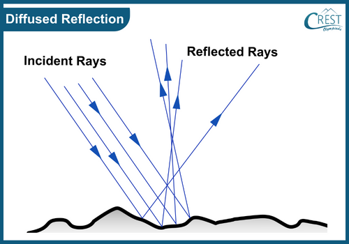
    2. Diffused Reflection

    a) Diffused reflection occurs on rough or uneven surfaces like walls or fabrics.
    b) When light strikes these surfaces, it scatters in various directions due to the uneven texture.
    c) This type of reflection produces a less defined and hazy reflection, as the light rays don't bounce off in a specific pattern.
    d) Diffused reflection is why we can see objects that aren't shiny or smooth, such as seeing the details of a book cover or the colour of a painted wall.

    Diagram of Diffused Reflection - Science Grade 8

    Laws of Reflection

    1. The First Law of Reflection

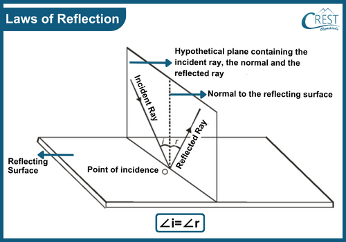
    a) The angle of incidence, angle of reflection, and the normal all lie on the same plane: This means that the incident ray, the reflected ray, and the normal line drawn perpendicular to the surface of reflection all exist within the same flat surface or plane.
    b) Incident ray: The incoming ray of light.
    c) Reflected ray: The ray of light that bounces off the surface.
    d) Normal: Imaginary line perpendicular to the surface where the light hits.

    2. The Second Law of Reflection

    a) The angle of incidence (∠i) is always equal to the angle of reflection (∠r): This means that if a ray of light strikes a surface at a certain angle, the angle at which it reflects off that surface will be exactly the same.
    b) Angle of incidence: The angle between the incident ray and the normal.
    c) Angle of reflection: The angle between the reflected ray and the normal.

    Laws of Reflection - Science Grade 8

    Differences Between a Real Image and a Virtual Image

    Aspect

    Real Image

    Virtual Image

    Formation

    Formed by the actual convergence of light rays.

    Formed by the apparent divergence of light rays.

    Projection

    Can be projected onto a screen or surface.

    Cannot be projected onto a screen or surface.

    Interaction

    Created by light rays actually coming together.

    Created by the way our eyes perceive light rays.

    Location

    Exists at a specific point in space.

    Appears to be located behind the mirror/lens.

    Capturing

    Can be captured using a physical device.

    Cannot be captured on a screen or paper.

    Orientation

    Usually inverted (upside-down) compared to the object.

    Can be either upright or inverted.

    Optical Devices

    Formed by concave mirrors, converging lenses, etc.

    Formed by convex mirrors, diverging lenses, etc.

    Examples

    An image formed on a movie screen.

    Image seen in a rear-view mirror.

    Plane Mirrors

    A plane mirror is a special type of mirror that possesses a flat and smooth surface. This mirror is crafted by depositing a thin layer of reflective material, like silver or aluminium, onto one side of a flat glass pane.

    When you gaze into a plane mirror, it works by reflecting the incoming light onto its surface. This reflection allows you to observe yourself or objects positioned in front of the mirror.

    Characteristics of an Image Formed by a Plane Mirror

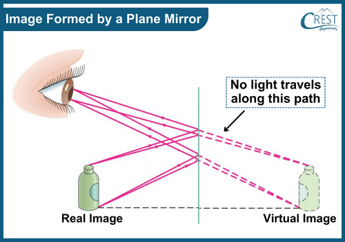
    Virtual Image: The image in a plane mirror is virtual, not a real object. It's an optical illusion created by the reflection of light. The image appears to be located behind the mirror, but there's no physical object there.

    Laterally Inverted: The image is laterally inverted, meaning the left and right sides of the image appear reversed compared to the actual object. This creates a horizontal flip in the image.

    Same Size: The image is the same size as the object being reflected. If the object is 1 meter tall, the image will also be 1 meter tall, maintaining proportional dimensions.

    Upright: The image is always upright, maintaining the same orientation as the object being reflected. If the object is held upright, its image in the mirror will also be upright.

    Formed at the Same Distance: The image is formed at the same distance behind the mirror as the object is in front of it. The distance between the mirror and the object is equal to the distance between the mirror and the virtual image.

    Diagram of Image Formed by a Plane Mirror - Science Grade 8

    Formation of Multiple Reflections by Plane Mirrors

    Multiple reflections occur when light bounces back and forth between different reflective surfaces. Imagine standing in front of a mirror and seeing your reflection. This reflected image can bounce off another mirror or surface, creating a series of reflections that seem to extend into the distance. This phenomenon is also known as successive reflections.

    Parallel Mirrors

    When two plane mirrors are positioned parallel to each other, regardless of their tilting, they produce an infinite sequence of images. This fascinating effect is often referred to as the "infinity mirror." The light bounces back and forth between the mirrors, generating reflections that appear to continue endlessly. With each reflection, the light energy diminishes slightly, resulting in progressively dimmer images.

    Non-Parallel Mirrors

    The formation of multiple images between two inclined plane mirrors is influenced by the angle between them.

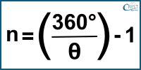
    a) If the angle between the mirrors is such that dividing 360 degrees by that angle (θ) yields an even number, the formula to determine the number of images (n) is:

    Formation of Multiple Reflections by Plane Mirrors - Science Grade 8

    For example, if the angle is 60 degrees:

    n = (360 / 60) - 1
    n = 6 - 1
    n = 5

    In this case, you would observe 5 images of the object.

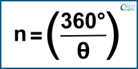
    b) If the angle between the mirrors, when divided into 360 degrees, results in an odd number, and the object is positioned exactly in the middle of that angle, the formula to calculate the number of images (n) is:

    Formation of Multiple Reflections by Plane Mirrors - Formula

    For example, if the angle is 24 degrees and the object is placed at the angle's bisector:

    n = (360 / 24)
    n = 15

    Here, you would observe 15 images of the object.

    Applications of Multiple Image Formation

    Multiple reflections have practical applications in various scenarios:

    a) Periscope: A periscope is an optical instrument that employs multiple reflections to allow someone to view objects that are not in their direct line of sight. It's commonly used in submarines, armoured vehicles, and even in some sports events. By using a series of mirrors, a periscope can reflect light from the surroundings, enabling someone to see objects located above or around obstacles.

    b) Kaleidoscope: A kaleidoscope is a decorative device that uses multiple reflections to create intricate and colourful patterns. Inside a kaleidoscope, there are usually three mirrors arranged in a triangular formation. When light enters through a small hole and reflects off these mirrors, it creates a symmetrical pattern that changes as you rotate the kaleidoscope. This simple yet fascinating device is often used as a form of artistic entertainment.

    c) Barbershop Mirror: In a barbershop, mirrors are strategically placed to allow barbers to see the back of a person's head while cutting their hair. These mirrors reflect the image of the person's head from different angles, giving the barber a clear view of areas that are typically harder to see.

    Spherical Mirrors

    Spherical mirrors are unique mirrors with curved surfaces resembling the inside of a spoon or a ball. There are two primary types: concave and convex mirrors.

    Concave Mirrors

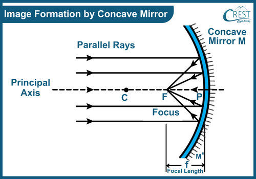
    Concave mirrors curve inward like the inside of a spoon. When light from an object hits them, the rays reflect and meet at a point known as the "focus" (F) in front of the mirror. Placing a screen at the focus shows a clear, magnified image.

    For concave mirrors, F is located at half the radius of curvature (f = R/2).
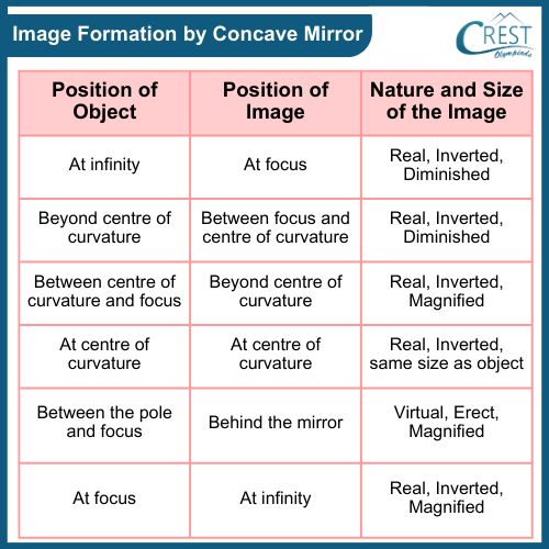
    Beyond the focus, real and inverted images form between the focus and the mirror.
    Between the focus and the mirror, virtual and magnified images arise.

    Image Formation by Concave Mirror

    Diagram of Image Formation by Concave Mirror - Science Grade 8

    Image Formation by Concave Mirror - Science Grade 8

    Applications of Concave Mirrors

    1. Reflective Telescopes: Magnify distant celestial objects
    2. Car Headlights: Provide focused light for better nighttime visibility
    3. Makeup and Shaving Mirrors: Allow detailed viewing
    4. Dentistry: Enhance visibility in oral procedures.

    Convex Mirrors

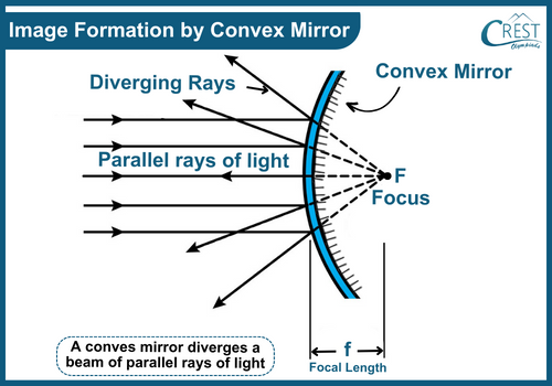
    Convex mirrors curve outward like the back of a spoon. When light hits them, it scatters, creating smaller images.

    The focal point (F) is located behind the mirror, at half the radius of curvature (f = R/2).
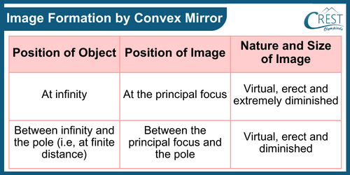
    Convex mirrors produce virtual, upright, and smaller images.

    Image Formation by Convex Mirror

    Diagram of Image Formation by Convex Mirror - Science Grade 8

    Image Formation by Concave Mirror - Science Grade 8

    Applications of Convex Mirrors

    1. Rear-View Mirrors: Offer a wider field of view for safer driving
    2. Security and Surveillance: Enhance security in public areas
    3. Road Safety: Installed at intersections to reduce accidents

    Refraction of Light

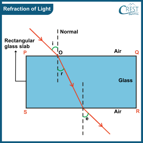
    Refraction of light refers to the phenomenon where light changes its direction as it passes from one medium to another. This change in direction is due to the difference in the speed of light in different mediums.

    When a light goes from a rarer (less dense) medium to a denser (more dense) medium, like from air to water, it slows down and bends towards the normal. This causes the light ray to slow down and change its direction.

    Conversely, when light passes from a denser medium to a rarer medium, it bends away from the normal. This happens because the light ray speeds up when it enters the rarer medium.

    Diagram of Refraction of Light - Science Grade 8

    Refractive Index

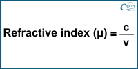
    The refractive index (often denoted by µ) of a material is a measure of how much light bends or refracts when it enters that material. It is defined as the ratio of the speed of light in a vacuum or air (c) to the speed of light in the medium (v).

    Mathematically,

    Formula of Refractive Index - Science Grade 8

    Relation between Real and Apparent Depth

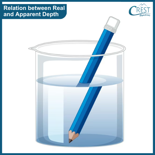
    Refractive index also affects the depth of an object submerged in a transparent medium. Real depth refers to the actual distance between two points on an object in a particular medium, while apparent depth is how the object appears to us when we observe it from another medium.

    When an object is placed in a medium like water, light from the object enters our eyes after passing through the water. However, due to the refraction of light at the water-air interface, the light rays change their direction, making the object appear shifted or displaced from its actual position. This effect creates an illusion, where the object seems to be at a different depth than it actually is.

    Example: Consider a pencil placed vertically in a glass filled with water. When you look at the pencil from above the water's surface, the light rays coming from the pencil undergo refraction as they pass from water to air, making the pencil appear bent or broken at the water's surface. This bent appearance gives you the impression that the pencil is not where it actually is. The bottom part of the pencil, which is submerged in water, appears to be shifted relative to its actual position due to the refraction of light.

    Relation between Real and Apparent Depth - Science Grade 8

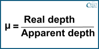
    The relation between real depth (actual depth of the object) and apparent depth (how deep it appears) is given by:

    Formula of Relation between Real Depth and Apparent Depth - Science Grade 8

    This relation shows how much the light is bent at the interface between the two mediums.

    Dispersion

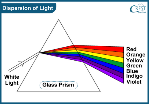
    Dispersion is a phenomenon that occurs when white light (which is composed of different colours) passes through a prism. The different colours in white light have different refractive indices in the prism.

    Consequently, the different colours undergo refraction at varying degrees and disperse, giving rise to a range of colours known as a spectrum. This spectrum encompasses the colours of the rainbow, often remembered by the acronym VIBGYOR, representing violet, indigo, blue, green, yellow, orange, and red.

    Dispersion is what causes the separation of colours in phenomena like rainbows and the splitting of light in a prism.

    Diagram of Dispersion of Light - Glass Prism

    Lenses

    A lens is an optical device made of transparent material, like glass or plastic, that has curved surfaces. At least one of these surfaces is curved, which allows the lens to bend or refract light as it passes through.

    Lenses are used to focus, diverge, or change the direction of light, depending on their shape and curvature.

    Types of Lenses

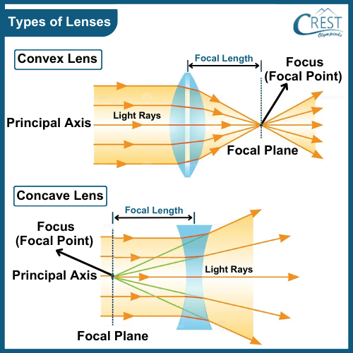
    Different Types of lenses - Concave and Convex Lens

    Convex Lens (Converging Lens)

    a) A convex lens is thicker at the centre and thinner at the edges. It bulges outward, resembling a magnifying glass.
    b) When parallel rays of light pass through a convex lens, they converge or come together at a single point on the opposite side. This point is called the focal point.
    c) Convex lenses are commonly used to bring light rays together, creating a focused image. They are often used in magnifying glasses, cameras, and telescopes.

    Concave Lens (Diverging Lens)

    a) A concave lens is thinner at the centre and thicker at the edges. It curves inward, like the hollow part of a spoon.
    b) When parallel rays of light pass through a concave lens, they diverge or spread out as if coming from a point on the same side as the incident light. This point is called the virtual focus.
    c) Concave lenses are used to spread out light rays and create images that appear smaller and farther away. They are commonly used in eyeglasses for nearsightedness.

    Ray Diagram Rules for Lenses

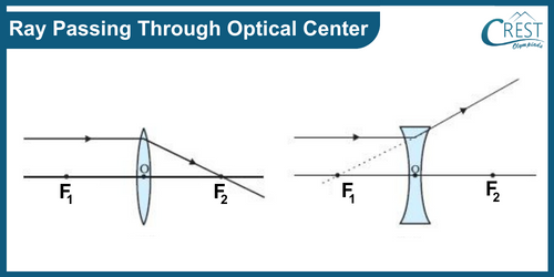
    1. Ray Passing Through Optical Center: When a ray of light passes through the optical center of a lens, it continues to travel in a straight line without any deviation. This rule applies to both concave and convex lenses.

    Ray Passing Through Optical Center - Ray Diagram Rules for Lenses

    2. Ray Parallel to Principal Axis

    a) When a ray of light approaches a lens parallel to its principal axis, the refracted ray will either pass through or appear to come from the focal point on the opposite side of the lens.
    b) For a concave lens, the refracted ray will appear to come from the focal point on the same side of the lens from which the light is coming.
    c) For a convex lens, the refracted ray will actually pass through the focal point on the opposite side of the lens.

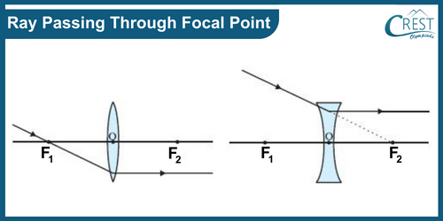
    3. Ray Passing Through Focal Point

    a) When a ray of light passes through the focal point of a lens, it will refract and emerge parallel to the principal axis on the other side of the lens.
    b) For a convex lens, the incident ray should be initially parallel to the principal axis to pass through the focal point on the other side.
    c) For a concave lens, the incident ray should be extended backwards to appear as if it is coming from the focal point on the opposite side.

    Ray Passing Through Focal Point - Ray Diagram Rules for Lenses

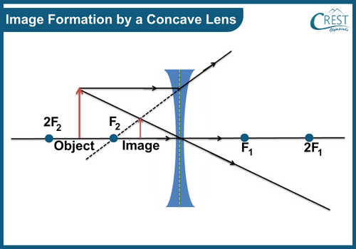
    Image Formation by a Concave Lens

    Image Formation by Concave Lens - Ray Diagram Rules for Lenses

    a) When light rays from an object fall on a concave lens, they diverge after refraction.
    b) This type of lens, known as a diverging or concave lens, always forms a virtual image that is erect (upright) and diminished (smaller than the object).
    c) The image is located between the optical centre of the lens and its focus. Unlike the images formed by converging lenses (convex lenses), the images formed by concave lenses cannot be projected onto a surface, as they are virtual and not real.

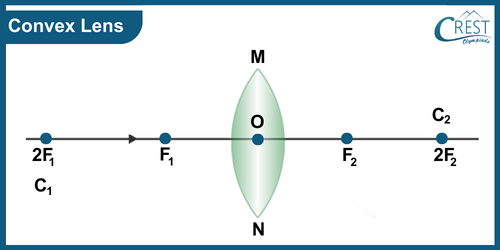
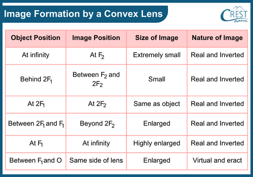
    Image Formation by a Convex Lens

    Convex Lens - Image Formation by a Convex Lens

    Image Formation by a Convex Lens - Science Grade 8

    The Human Eye

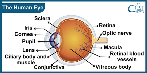
    The human eye is a remarkable sensory organ that enables us to perceive the world through the sense of vision. It functions by capturing light and converting it into signals that the brain interprets as images.

    Labelled Diagram of Human Eye - Science Grade 8

    Parts of the Eye

    Cornea: The transparent outer layer at the front of the eye, the cornea, helps to focus incoming light and protects the eye.

    Iris and Pupil: Behind the cornea, the iris controls the size of the pupil, the central dark opening. The pupil adjusts in response to light levels, regulating the amount of light that enters the eye.

    Lens: The lens, located behind the pupil, further focuses incoming light onto the retina. It can change its shape to adjust focus for objects at different distances.

    Ciliary Muscles: These muscles control the shape of the lens, allowing it to adjust focus. This process is called accommodation.

    Retina: The retina, at the back of the eye, contains specialized cells called photoreceptors. These cells convert light into electrical signals that the brain can understand.

    Rods and Cones: Photoreceptors are divided into rods and cones. Rods function in low light and provide black-and-white vision, while cones work in bright light and enable colour vision.

    Blind Spot: The optic nerve, which transmits visual signals to the brain, leaves the eye through a small area on the retina known as the blind spot. This area lacks photoreceptors, so it doesn't contribute to vision.

    Aqueous Humour: The space between the cornea and the lens is filled with a clear fluid called aqueous humour, which maintains eye pressure and nourishes the cornea.

    Vitreous Humour: The larger space between the lens and the retina is filled with a jelly-like substance called the vitreous humour. It maintains the eye's shape and contributes to its optical properties.

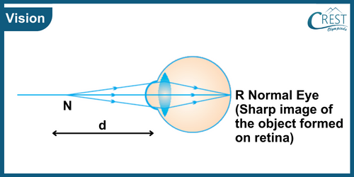
    Image Formation: Light entering the eye is focused by the cornea and lens onto the retina. The photoreceptors in the retina convert light into electrical signals.

    Optic Nerve: The electrical signals from the retina travel through the optic nerve to the brain's visual cortex for interpretation.

    Defects of Vision

    Vision defects, also known as refractive errors, are conditions that affect the ability of the eye to properly focus light onto the retina, leading to blurred or distorted vision.

    Defects of Vision or Refractive Errors- Science Grade 8

    Here are two common types of refractive errors:

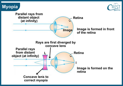
    a) Myopia (Nearsightedness): Myopia is a condition where distant objects appear blurry, while close objects can be seen clearly. This occurs when the eyeball is too long or the cornea is too curved. As a result, light entering the eye focuses in front of the retina instead of directly on it. Myopic individuals can see near objects clearly but need corrective lenses (glasses or contact lenses) to see distant objects clearly.

    Labelled Diagram of Myopia or Nearsightedness - Science Grade 8

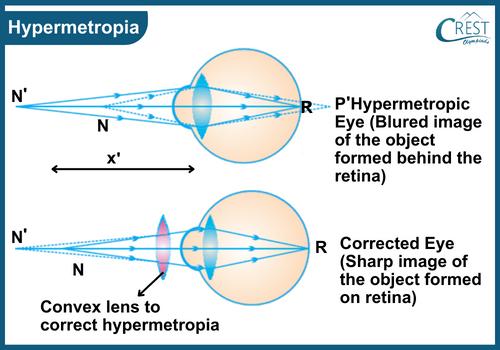
    b) Hypermetropia (Farsightedness): Hypermetropia is a condition where near objects appear blurry, while distant objects may be seen more clearly. This happens when the eyeball is too short or the cornea is too flat, causing light to focus behind the retina. Hypermetropic individuals might experience difficulties with close-up tasks and may need corrective lenses for both near and distant vision.

    Labelled Diagram of Hypermetropia - Science Grade 8

     Suggested - Explore more about Sound

    Share Your Feedback

    CREST Olympiads has launched this initiative to provide free reading and practice material. In order to make this content more useful, we solicit your feedback.

    Do share improvements at info@crestolympiads.com. Please mention the URL of the page and topic name with improvements needed. You may include screenshots, URLs of other sites, etc. which can help our Subject Experts to understand your suggestions easily.

    Other Science Related Topics for Class 8

    70%